I do not know if it is "the best return on investment" business practice or the fact that programming and CPU's are replacing the analog electronics; but the fact is that nowadays it is almost impossible to find potentiometers with odd values, odd tapers (log/rev log), or unusual terminal arrangements. I usually buy my components from Mouser which is a typical worldwide distributor of electronic components. Here is a typical search from Mousers online catalog:
Potentiometers --> 7558 matches
Stocked --> 2240 matches (where did they all go!)
Resistance=10k and taper=linear --> 349 matches
Still plenty of where to choose from.
Let's next try to find a 1M logarithmic potentiometer:
Resistance=1M and taper=logarithmic --> 25 matches
Okay, that's not very much. From these 25 I need a version that fits directly to my PCB
Termination Style=Pin --> 7 matches
This is a problem, if I want specific power rating, mounting arrangement, shaft type …
How do we get it if we can't buy it ? Tapering/loading resistors may be the answer. When a fixed resistor is connected between the wiper and ccw-lug of linear potentiometer it's behaviour changes from linear to logarithmic. If the resistor is connected between wiper and cw-lug we get reverse logarithmic behaviour. So with different tapering resistor and lin-pot arrangements it is possible to create different logarithmic potentiometers. You can also replace the fixed tapering resistor with a trimmer and adjust the exact potentiometer behaviour that you want. Pictured below I have measured and plotted some 50k lin and log potentiometers. I printed a 360° scale on a plane where the potentiometer is set up. I measured the resistance between the wiper and cw-lug by moving the potentiometer 28 identical times (28 x 10° = 280° --> effective electrical angle).
 |
| Notice the tapering resistor between wiper and cw-lug |
 |
| 360° scale |
 |
| Measurements of potentiometers |
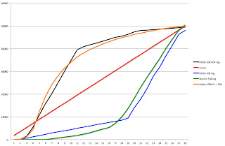
Red line shows the linear behaviour. As you can see Alpha 50k log pot (blue line) is a cheap potentiometer where logarithmic behaviour is approximated with two linear segments (turning point at 19). You can compare it to Bourns 50k log pot (green line) which has more smooth logarithmic behaviour. Alpha 50k REV log pot (black line) is a real reverse logarithmic potentiometer. It seems that it's behaviour is approximated with three linear segments (turning points 10.5 and 20.5). Alpha 100k lin + 20k is my experiment with 100k linear potentiometer with 20k fixed tapering resistor between the wiper and cw-lug (orange line). As you can see it approximates nicely the reverse logarithmic behaviour of Alpha's real REV log potentiometer (it is actually much smoother). With two terminal (series) connection and tapering resistor you can get only reverse logarithmic behaviour out of the potentiometer. With three terminal (voltage divider) connection it is possible to get the log/rev-log behaviour depending if you connect the tapering resistor between cw or cww lug of potentiometer. There is also one thing that must be remembered. Total resistance of the potentiometer is smaller when using the tapering resistor. It is a normal parallel resistor connection. In my experiment 100k + 20k tapering resistor gives 16.7k total resistance (I have scaled it so that it fits in this same picture with the 50k potentiometers).
Moog Prodigy's most critical potentiometer is the filter cutoff pot that is originally a 50k reverse logarithmic potentiometer. I can use here only linear potentiometer so I must experiment with this tapering resistor method to get the exact feel that I want for the cutoff pot.
Here is a good article about potentiometers and their tapering (
http://www.geofex.com/article_folders/potsecrets/potscret.htm).